Mfr Part # 15191
RFID QWIIC READER
SparkFun Electronics
Wireless RFID / NFC Arduino Qwiic
Guide by Elias The Sparkiest
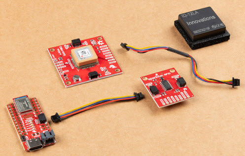
The Qwiic RFID ID-XXLA is an I2C solution that pairs with the ID-LA modules: ID-3LA, the ID-12LA, or the ID-20LA, and utilizes 125kHz RFID chips. Using the product's interrupt pin, we'll discuss how to get, store, and compare unique RFID IDs. Let's take a look at the hardware used for this RFID tutorial.
To follow along with this tutorial, you will need the following materials. You may not need everything though depending on what you have. Add it to your cart, read through the guide, and adjust the cart as necessary.
Heads up! For the scope of the tutorial, we will be using the ID-12LA RFID reader. The board is also compatible with the following ID-xxLA modules at 125kHz. The range varies with each model. Keep in mind that you will need to an external antenna for the ID-3LA.
The following RFID tags are also compatible with the RFID reader.
You will need a soldering iron, solder, and general soldering accessories.
If you aren't familiar with the Qwiic system, we recommend reading here for an overview.
We would also recommend taking a look at the following tutorials if you aren't familiar with them.
This is a Qwiic product but not a "pure" Qwiic product. You'll still need to solder or connect the interrupt pin if you decide to use that to indicate when an RFID card has been read (more on that later). Outside of that, Qwiic is an eco-system designed for I2C devices that allows you to prototype quickly without needing to solder anything. Just plug your Qwiic product into a Qwiic capable microcontroller and you're good to go! There are two on this product which means you can daisy chain the product with other I2C devices, like a Qwiic Keypad for example.

The SparkFun Qwiic RFID ID-xxLA is a 3.3V system. You can power the product with a Qwiic cable plugged into a capable microcontroller. You can also provide power through the 3V3 pin on the header.
When you provide power to the board you will see the onboard red power LED light up. There's another LED opposite the power LED labeled READ. This blue stat LED and the onboard buzzer will light or beep respectively when an RFID tag is brought into range.

There are three ID-xxLA options in our catalog that are listed above in the Introduction: the ID-3LA, the ID-12LA, and ID-20LA. If you purchased the SparkFun RFID kit then it includes the ID-12LA and RFID cards that you need. Pictured below is the ID-12LA plugged into the Qwiic RFID.

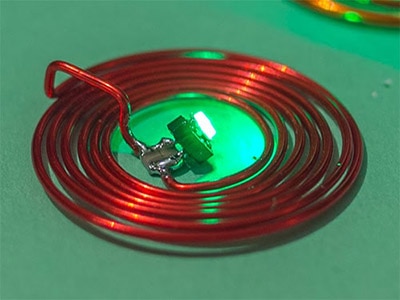
Each option is similar but there is a small variance in power consumption which translates into different read range capabilities. The ID-3LA is designed to be used with an external antenna which will get you 30cm of range. The ID-12LA and ID-20LA have a range of 12cm and 18cm respectively.
When plugging in your module, just take care that the side with less pins goes into the header with less pins.
 Smaller header on the left, larger on the right.
There are four jumpers on the header side of the product. Facing the product with the buzzer at the top, you'll see a jumper on the left side labeled INT. The interrupt pin can be disconnected here by cutting the trace. Now moving to the bottom near the header is a jumper labeled I2C that connects the I2C pull-up resistors to the I2C data lines. On the right side is a jumper labeled Buzzer that disconnects the buzzer when cut. This will disable the beeping sound when a RFID card is in range. Finally, the ADDR jumper allows you to change the default I2C jumper from 0x13 to 0x14.

Note: As ofv1.2.0, the default address is 0x13 and the alternative address is 0x14 in the SparkFun Qwiic RFID Arduino Library. Previously, the default address was 0x7D and the alternative address was 0x7C.
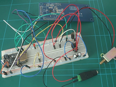
Simply insert a Qwiic cable between the RedBoard Qwiic and the Qwiic RFID reader. You will also need to solder wire between the Qwiic RedBoard's pin 8 and the Qwiic RFID reader's INT pin. When you are ready, align the headers of the module with the Qwiic RFID reader.

Note: The Qwiic system has a logic level of 3.3V. I have attached the interrupt to pin 8 on the RedBoard Qwiic even though the pin is at 5 volts. This will not harm the Qwiic RFID because we're doing a simple digitalRead() but also because the ATTiny84 is tolerant of voltages up to 5.5V.
We've written a library to make it even easier to get started with the SparkFun Qwiic RFID ID-XXLA. The library will give you the full functionality of the Qwiic RFID ID-XXLA without the hub bub of the I²C data transactions. Also included are examples codes to demonstrate the full functionality of the library. You can click the link below to download the file directly and install it manually, or navigate through the Arduino Library Manager by searching SparkFun Qwiic RFID. You can also go the GitHub page and get download it from there.
SparkFun Qwiic RFID Arduino Library (ZIP)
Note: This example assumes you are using the latest version of the Arduino IDE on your desktop. If this is your first time using Arduino, please review our tutorial on installing the Arduino IDE. If you have not previously installed an Arduino library, please check out our installation guide.
Let's take a look at the first two example sketches provided in the SparkFun Qwiic RFID Arduino Library.
For this first example we'll be grabbing the scanned card and the time between when it was scanned and when we request the number, by typing the number 1 into the Arduino IDE's Serial Terminal. If you downloaded the SparkFun Qwiic RFID Arduino Library directly then open the example located in the in the examples folder: SparkFun_Qwiic_RFID_Arduino_Library > Examples >Example1_Read_Tag_Basics.ino . If you've downloaded the library through the Arduino Library Manager, then in the Arduino IDE you can navigate to File>Examples>SparkFun Qwiic RFID Arduino LIbrary>Example1_Read_Tag_Basics.
Let's walk through the setup at the very top of the code. Nothing too surprising here, we've #included-ed the Wire library as well as the SparkFun Qwiic RFID library. We then initialize the library with the Qwiif Rfid myRfid(RFID_ADDR) declaration. You may notice that it takes the Qwiic RFID Reader's address as one of its arguments: RFID_ADDR. In the setup we begin the Wire, Serial, as well as the Qwiic RFID library. If there is a problem between your RedBoard and the SparkFun Qwiic RFID board, then we'll print out an error message.
#include <Wire.h>
#include "SparkFun_Qwiic_Rfid.h"

//#define RFID_ADDR 0x7D // Old Default I2C Address
#define RFID_ADDR 0x13 // Default I2C address

Qwiic_Rfid myRfid(RFID_ADDR);

String tag;
float scanTime;
int serialInput;

void setup()
{
    Wire.begin();
    Serial.begin(115200);
    Serial.println("Example 1 Read Tag Basics.");

    if(!myRfid.begin()){
        Serial.println("Could not communicate with Qwiic RFID, check you have the correct address!");
        while(1)
    }

    Serial.println("Ready to scan some tags!");

    // Want to clear tags sitting on the Qwiic RFID card?
    //myRfid.clearTags();
}
In the main loop, we're looking for the number 1 to be entered into the Serial terminal. When that's entered we're going to grab the RFID tag with the myRFId.getTag() function call and get its' "scan" time (in seconds) with the myRFID.getPrecReqTime() function call. Just a quick note on the "time". This is not the time of day the tag was scanned but rather the time between when it was scanned and when you requested it. This gives each RFID tag a unique property even when you scan the same card twice, because their scan times will be different.
void loop()
{
  if (Serial.available() > 0){

    serialInput = Serial.read();
    if (serialInput == 49){   // "1" on your keyboard is 49 in ASCII

      tag = myRfid.getTag();
      Serial.print("Tag ID: ");
      Serial.print(tag);
      scanTime = myRfid.getPrecReqTime();
      // If this time is too precise try:
      // long time = myRfid.getReqTime();
      Serial.print(" Scan Time: ");
      Serial.println(scanTime);

    }

  }
}
After scanning a card and waiting a number of seconds, then entering 1 into the Serial Terminal, my output looks like this.

If you need a similar example, but one that reads all 20 tags that can be stored on the SparkFun Qwiic RFID ID-XXLA Reader, then check out Example5_Get_All_Available_Tags.
For this next example we'll be using an additional pin as an interrupt that will indicate that a card has been scanned, which makes this not a pure Qwiic example. We'll use that interrupt to initiate a request to read the tag that the SparkFun Qwiic RFID Reader is holding onto. If you the downloaded the SparkFun Qwiic RFID Arduino Library directly then open the example located in the in the examples folder: SparkFun_Qwiic_RFID_Arduino_Library > Examples >Example2_Read_Tag_Interrupt.ino . If you've downloaded the library through the Arduino Library Manager, then in the Arduino IDE you can navigate to File>Examples>SparkFun Qwiic RFID Arduino LIbrary>Example2_Read_Tag_Interrupt.
At the top we #include the new library and use the default address for our Qwiic Rfid myRfid(RFID_ADDR) declaration. In the setup we communicate with the SparkFun Qwiic RFID Reader with the myRfid.begin statement. If there is any issue communicating with the Qwiic RFID we'll know about them here. Last but not least we pull the interrupt pin on pin 3 up high with pinMode(intPin, INPUT_PULLUP) to put it into a known HIGH state. When a tag is read this line will go LOW.
#include <Wire.h>
#include "SparkFun_Qwiic_Rfid.h"

//#define RFID_ADDR 0x7D // Old Default I2C Address
#define RFID_ADDR 0x13 // Default I2C address

// Interrupt Pin on pin 3.
const int intPin = 3;
String tag;

Qwiic_Rfid myRfid(RFID_ADDR);

void setup()
{
    Wire.begin();
    Serial.begin(115200);
    Serial.println("Example 2 - Read RFID Tag on Interrupt");

    if(!myRfid.begin()){
        Serial.println("Could not communicate with Qwiic RFID, check you have the correct address!");
        while(1)
    }

    Serial.println("Ready to scan some tags!");

    // Put the interrupt pin in a known HIGH state.
    pinMode(intPin, INPUT_PULLUP);

    // Want to clear tags sitting on the Qwiic RFID card?
    //myRfid.clearTags();

}
In the loop, we're just monitoring the Qwiic RFID's interrupt pin that will indicate that a tag has just been read. This will initiate a call to myRfid.getTag() that will pull in the scanned card's RFID tag ID.
void loop()
{

    // If the pin goes low, then a card has been scanned.
    if(digitalRead(intPin) == LOW){
        tag = myRfid.getTag();
        Serial.println(tag);
    }

    delay(500);

}
And that's it!
If you have not already, select the board and COM port of your Arduino and upload the Example1_ReadTag.ino code. Then open your Serial Monitor at 115200 and scan a tag.

You should see the following. Note at the image indicates a baud rate of 9600 but the latest code uses a baud rate of 115200.

Note: This tutorial assumes you are using the latest version of Python 3. If this is your first time using Python or I2C hardware on a Raspberry Pi, please checkout our tutorial on Python Programming with the Raspberry Pi and the Raspberry Pi SPI and I2C Tutorial. Jetson Nano users can check out this tutorial on Working with Qwiic on a Jetson Nano through Jupyter Notebooks.
We've written a Python package to easily get setup and take readings from the ID-LA RFID module. There are two methods for installing the Python package for the Qwiic RFID.
The all-inclusive SparkFun Qwiic Python package, is recommended as is also installs the required I2C driver as well.
Note: Don't forget to double check that the hardware I2C connection is enabled on your single board computer.
This repository is hosted on PyPi as the sparkfun-qwiic package. On systems that support PyPi installation via pip3 (use pip for Python 2) is simple, using the following commands:
For all users (note: the user must have sudo privileges):
sudo pip3 install sparkfun-qwiic
For the current user:
pip3 install sparkfun-qwiic
You can install the sparkfun-qwiic-rfid Python package independently, which is hosted by PyPi. However, if you prefer to manually download and install the package from the GitHub repository, you can grab them here (*Please be aware of any package dependencies. You can also check out the repository documentation page, hosted on ReadtheDocs.):
Download the SparkFun Qwiic RFID Python Package (ZIP)
This repository is hosted on PyPi as the sparkfun-qwiic-rfid package. On systems that support PyPi installation via pip3 (use pip for Python 2) is simple, using the following commands:
For all users (note: the user must have sudo privileges):
sudo pip3 install sparkfun-qwiic-rfid
For the current user:
pip3 install sparkfun-qwiic-rfid
To install, make sure the setuptools package is installed on the system.
Direct installation at the command line (use python for Python 2):
python3 setup.py install
To build a package for use with pip3:
python3 setup.py sdist
A package file is built and placed in a subdirectory called dist. This package file can be installed using pip3.
cd dist
pip3 install sparkfun_qwiic_rfid-<version>.tar.gz
Before we jump into getting readings, let's take a closer look at the available functions in the Python package. Below, is a description of the basic functionality of the Python package. This includes the package organization, built-in methods, and their inputs and/or outputs. For more details on how the Python package works, check out the source code and package documentation.
This Python package has a very few dependencies in the code, listed below:
import qwiic_i2c
import time
The default variables, in the code, for this Python package are listed below:
# qwiic_rfid GLOBAL VARIABLES
#----------------------------------------------------------------------------------------------------
# Define the device name and I2C addresses. These are set in the class defintion
# as class variables, making them avilable without having to create a class instance.
# This allows higher level logic to rapidly create a index of qwiic devices at
# runtine
#
# The name of this device
_DEFAULT_NAME = "Qwiic RFID"

# Some devices have multiple availabele addresses - this is a list of these addresses.
# NOTE: The first address in this list is considered the default I2C address for the
# device.
_AVAILABLE_I2C_ADDRESS = [0x13, 0x14]
Note: This package is different from previous packages as the register variables are declared in the object class.
# QwiicRFID CLASS VARIABLES
#----------------------------------------------------------------------------------------------------
ALTERNATE_ADDR = 0x7C
ADDRESS_LOCATION = 0xC7

TAG_AND_TIME_REQUEST = 10
MAX_TAG_STORAGE = 20
BYTES_IN_BUFFER = 4

RFID_TAG = None
RFID_TIME = None
TAG_ARRAY = [None] * MAX_TAG_STORAGE
TIME_ARRAY = [None] * MAX_TAG_STORAGE
QwiicRFID() or QwiicRFID(address)
This Python package operates as a class object, allowing new instances of that type to be made. An __init__() constructor is used that creates a connection to an I2C device over the I2C bus using the default or specified I2C address.
A constructor is a special kind of method used to initialize (assign values to) the data members needed by the object when it is created.
__init__(address=None, i2c_driver=None):
Input: value
The value of the device address. If not defined, the Python package will use the default I2C address (0x13) stored under _AVAILABLE_I2C_ADDRESS variable.
Input: i2c_driver
Loads the specified I2C driver; by default the Qwiic I2C driver is used: qwiic_i2c.getI2CDriver(). Users should use the default I2C driver and leave this field blank.
A function is an attribute of the class, which defines a method for instances of that class. In simple terms, they are objects for the operations (or methods) of the class. A list of all the available functions are detailed on the API Reference page of ReadtheDocs for the Qwiic_RFID_Py Python package.
In the future, changes to the Python package might be made. Updating the installed packages has to be done individually for each package (i.e. sub-modules and dependencies won't update automatically and must be updated manually). For the sparkfun-qwiic-rfid Python package, use the following command (use pip for Python 2):
For all users (note: the user must have sudo privileges):
sudo pip3 install --upgrade sparkfun-qwiic-rfid
For the current user:
pip3 install --upgrade sparkfun-qwiic-rfid
Note: Work on this section is in progress. We will update the content as soon as we can.
Now that you've successfully got your Qwiic RFID Reader up and running, it's time to incorporate it into your own project! For more information, check out the resources below:
We carry other RFID options. Do you want a high powered RFID reader that can simultaneously pick up multiple RFID cards at a time? Perhaps you'd rather a RFID card reader that transmits over serial, check out the options below.